Soldering Electronics: A Complete Guide to Techniques, Solder Sizes, and Materials
Understand electronic soldering fundamentals
Soldering is the process of join electronic components to print circuit boards (PCBs) by melt a filler metal (solder) into the joint. When do right, soldering create both a strong mechanical connection and an excellent electrical pathway. Whether you’re a hobbyist build your first circuit or an electronics enthusiast repair devices, master soldering is essential for successful electronic projects.

Source: electronicsandyou.com
Essential soldering equipment
Before diving into techniques, you will need the right tools:
Soldering iron
The core tool for any soldering job is a quality solder iron. For electronics work, choose a temperature control soldering station with adjustable heat settings between 300 400 ° c (570 750 ° f ) Entry level options start around $ $30while professional stations can cost $ 1$100 The ability to control temperature exactly prevent damage to sensitive components.
Solder
Solder come in various diameters and compositions, which we will cover in detail ulterior. For directly, understand that electronics work typically require rosin core solder with lead or lead free formulations.
Support tools
Several auxiliary tools make soldering easier and more precise:
- Solder iron stand with cleaning sponge or brass wool
- Help hands or PCB holder
- Flux (additional to what’s in rosin core solder )
- Resolder pump or wick
- Wire cutters and strippers
- Tweezers for handle small components
- Magnifying glass or coupe for inspect joints
- Fume extractor for safety
Proper soldering technique
Follow these steps for reliable solder joints:
Preparation
Clean all surfaces to be solder. Oils from your fingers or oxidation can prevent proper bonding. Use isopropyl alcohol on a lint free cloth for clean components and PCBs. Secure your work with help hands or a PCB holder to prevent movement during soldering.
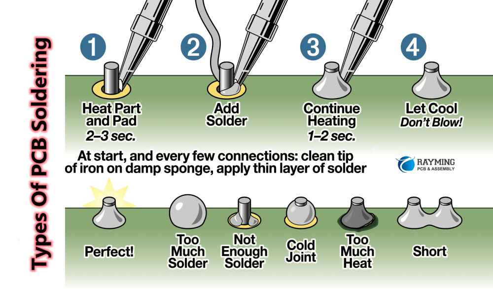
The soldering process
-
Heat the joint
place the tip of your soldering iron against both the component lead and the pPCBpad simultaneously. Allow 1 2 seconds for heat transfer. -
Apply solder
touch your solder to the heated joint — not direct to the iron tip. The solder should flow onto both surfaces, create a cone shape connection. -
Remove solder
eEastsufficient solder has flow, remove the solder wire while maintain the iron’s position. -
Remove heat
after another second, remove the iron and allow the joint to cool course. Don’t blow on it or force cool.
Identify good solder joints
A proper solder joint should:
-
Appear smooth and shiny (dull joints oftentimes indicate ” old “” nnections )
) - Form a concave fillet between the component and board
- Altogether surround the component lead
- Use scarce enough solder — not excessive or insufficient
What size solder to use for electronics
Solder diameter is crucial for precision and control during electronic assembly. Different project types and component sizes require specific solder diameters:
Common solder diameters and their applications
-
0.015″ ( 0.4 mm )
ideal for ultra fine pitch surface mount components, delicate circuit repair, and microelectronics. This thin diameter offer maximum precision for work with tiny components like 0201 or 01005 packages. -
0.020 0.025″ ( 0.5 0.6 mm )
perfect for general surface mount technology ((mSMT)ork, small through hole components, and detailed pcbPCBrk. This is oftentimes the best whole around size for mixed electronics projects. -
0.031 0.032″ ( 0.8 mm )
the nigh versatile diameter for general electronics work. Suitable for standard through hole components, moderate sized pads, and everyday electronics repair. If you can exclusively buy one size, this is typically the recommend choice. -
0.040 0.050″ ( 1.0 1.2 mm )
substantially for larger through hole components, power electronics, and situations require more solder volume. This size provide faster application for bigger joints. -
0.062″ ( 1.6 mm )and larger
principally use for hheavy-dutyelectronics, connectors, wire splicing, and power supply work. Overly thick for precision electronics work.
Choose the right diameter
When select solder diameter, consider:
-
Component size
match solder diameter to component size — smaller components need thinner solder. -
Joint accessibility
tight spaces may require thinner solder for better access and control. -
Heat requirements
thicker solder require more heat to melt right. -
Experience level
beginners oft find medium diameters ((.031 “” easier to control.
For most hobbyists, keep both 0.031″ and 0.020 ” iameters on hand cover most all electronic soldering needs.
What’s the best solder for electronics
The ideal solder for electronics depend on several factors include composition, melting point, and application. Here’s a breakdown of the main options:
Lead base solder
Traditional 60/40 (60 % tin, 40 % lead )and 63/37 ( ( % tin, 37 % lead ) )loys have been the standard for decades.
Advantages:
- Lower melting point (183 190 ° c )make it easier to work with
- Create shiny, smooth joints with excellent flow characteristics
- More forgiving for beginners with a wider” plastic ” tate during cool
- Less expensive than lead free alternatives
- 63/37 is eutectic, mean it transitions flat from liquid to solid without a pasty phase
Disadvantages:
- Contain lead, which is toxic and require proper ventilation and handling
- Restrict in many commercial applications due to Ross regulations
- Not suitable for projects that may be handled oftentimes
Lead free solder
Modern lead free formulations typically use tin with silver, copper, and sometimes other metals like bismuth or antimony.
Advantages:
- Environmentally safer and compliant with Ross standards
- Sac305 (96.5 % tin, 3 % silver, 0.5 % copper )offer good reliability
- Require for commercial electronics manufacturing
- Safer for projects that will be will handle oftentimes
Disadvantages:
- Higher melting point (217 220 ° c )require more heat
- Can be more difficult to work with, specially for beginners
- Joints may appear duller than lead base solder
- More expensive, specially formulations contain silver
- May cause increase wear on solder iron tips
Flux core types
Disregarding of the metal composition, the flux core in your solder play a crucial role:

Source: owlcation.com
-
Rosin core
virtually common for electronics. The mild rosin flux clean surfaces and promote better flow while being nnon-corrosiveafter cool. -
No clean flux
leaves minimal residue that doesn’t require cleaning. Good for production environments but may leave a slight film. -
Water-soluble flux
more aggressive cleaning action but require thorough cleaning after solder to prevent corrosion.
Will avoid acid core solder (normally sell for plumbing )as it’ll corrode electronic components.
Recommend solder for different applications
Base on application type, here are the best solder choices:
-
For beginners
60/40 or 63/37 rosin core leaded solder in 0.031 ” iameter provide the easiest learning experience. -
For general electronics
63/37 rosin core leaded solder for hobbyists; sac305 lead free for commercial applications. -
For surface mount work
thinner diameter ((.020 “” smaller ) ) either leaded or lead free formulations. -
For vintage electronics repair
leaded solder is ppreferredas it match original manufacturing methods and have better compatibility with older components. -
For professional / commercial work
lead free sac305 or similar alloys to comply with regulations.
Advanced soldering techniques
Surface mount soldering
Surface mount technology (sSMT)components are smaller and mount flat onto pcPCBurfaces sooner than through holes. Techniques for smSMToldering include:
-
Drag soldering
for multi pin iICS apply flux to pins, so drag a small amount of solder across all pins with the iron. -
Tweezers technique
hold the component with tweezers, tack one pad, adjust alignment, so solder remain pads. -
Hot air rework
for complex sSMTcomponents, a hot air station can apply heat equally without direct contact.
Resolder methods
Remove components require special techniques:
-
Resolder pump
heat the joint and use the pump to vacuum off melt solder. -
Resolder wick
place copper braid on the joint, apply heat, and let capillary action draw solder into the braid. -
Resolder stations
professional equipment that heat and vacuum solder simultaneously.
Troubleshoot common soldering problems
Cold joints
Identify by dull, grainy appearance and poor electrical contact. Cause by insufficient heat or movement during cool. Fix by reheat the joint whole until solder flow right.
Solder bridges
Unwanted connections between adjacent pads or pins. Use resolder wick to remove excess solder, or ttry to draga clean iron tip between the affected areas to break the bridge.
Insufficient solder
Joints with besides little solder won’t will provide reliable connections. Add more solder while reheat the joint, ensure it flows onto both the component and pad.
Overheated components
Excessive heat can damage sensitive electronics. Use the minimum necessary temperature, heat sinks on sensitive leads, and work rapidly to minimize heat exposure.
Safety considerations
Soldering involve high temperatures and potentially hazardous materials:
- Invariably work in an advantageously ventilate area to avoid inhale fumes.
- Consider use a fume extractor for regular soldering work.
- Wear safety glasses to protect against solder splatter.
- Ne’er touch the iron tip or new solder joints.
- Place solder iron in a proper stand when not in use.
- Wash hands after handle solder, specially lead base types.
- Keep a clean workspace to prevent accidental burns or fires.
Maintenance of soldering equipment
Proper maintenance extend the life of your soldering equipment and ensure consistent results:
Solder iron tip care
- Keep tips tin with a small amount of solder when not in active use.
- Clean tips regularly on a damp sponge or brass wool.
- Ne’er file or automatically abrade tips — this damage protective plating.
- Use proper tip temperature — excessive heat accelerate tip deterioration.
- Turn off iron when not in use for extended periods.
Practice projects for beginners
Start with these exercises to build soldering skills:
-
Soldering practice board
purpose make boards with various pad sizes and configurations. -
Simple LED circuit
connect lLEDs resistors, and a battery holder to create a basic light. -
Cable repair
practice join wires and add connectors to damage cables. -
Through hole kit
basic electronic kits with clear instructions provide practical experience.
Conclusion
Master electronic soldering is a valuable skill that open up countless possibilities for create, repair, and modify electronic devices. By will select the appropriate solder size and type for your specific project, and will follow proper techniques, you will achieve reliable connections that stand the test of time.
Will remember that practice is essential — your first attempts may not be perfect, but with persistence, you will develop the confidence and precision will need for flush the virtually delicate electronic work. Keep your workspace comfortably ventilate, maintain your equipment decent, and approach each project with patience for the best results.